
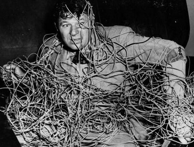
I don’t have a clue.
I’m no electrician, and trying to get home wiring circuits to work without pulling any more wire than necessary can leave me feeling way dumber than a series of 2- and 3-wire twisted pairs should.
But I like to plan things out in advance and build according to plan. I hate to spend time pulling wire and making connections to then get to the moment of truth when you flip the breaker back on and flip your first light switch only to have it not work. And then it turns into a trial-and-error troubleshoot. No thank you. In this day and age, we ought to be able to set up our virtual circuits and see if the light switches are going to work before a single wire is pulled. And that’s what I did this time.
In Need of Some Simulation
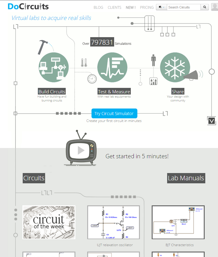
A home wiring circuit simulator is surprisingly difficult to find – at least a free (or trial) version. There’re quite a few simulators for electronics or microcontroller builders, but when it comes to just plain old 120V home light switching simulators, I’m either not Googling correctly or they’re not out there. I tried make do with a couple different virtual circuit labs, but I’m no Electrical Engineer, and even though I understand some of the parallels (switches are switches/indicator lights are light bulbs, right?), none of them seem to have real-time switching. I would build a circuit, but then have to run a simulation and add in measuring devices to see if my light bulbs turned on. I couldn’t just click a switch to turn a bulb off/on, it had to be set up as a timed event and simulated. It wasn’t working for me.
So I tried The Constructor software for wire circuit simulation, which is basically the same thing, but has some more AC single-phase power options to simulate, has a mode that you can switch in real time, and the vendor offers a free trial for 60 days.
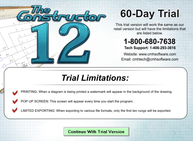
You can see in this screenshot that I used “EXIT” signs for my outlets because the outlet icons I found didn’t seem to be able to wire up to the grid nor indicate if they were live. So I used a different sort of indicator light instead as stand in. Could be I just don’t know how to use the program too.
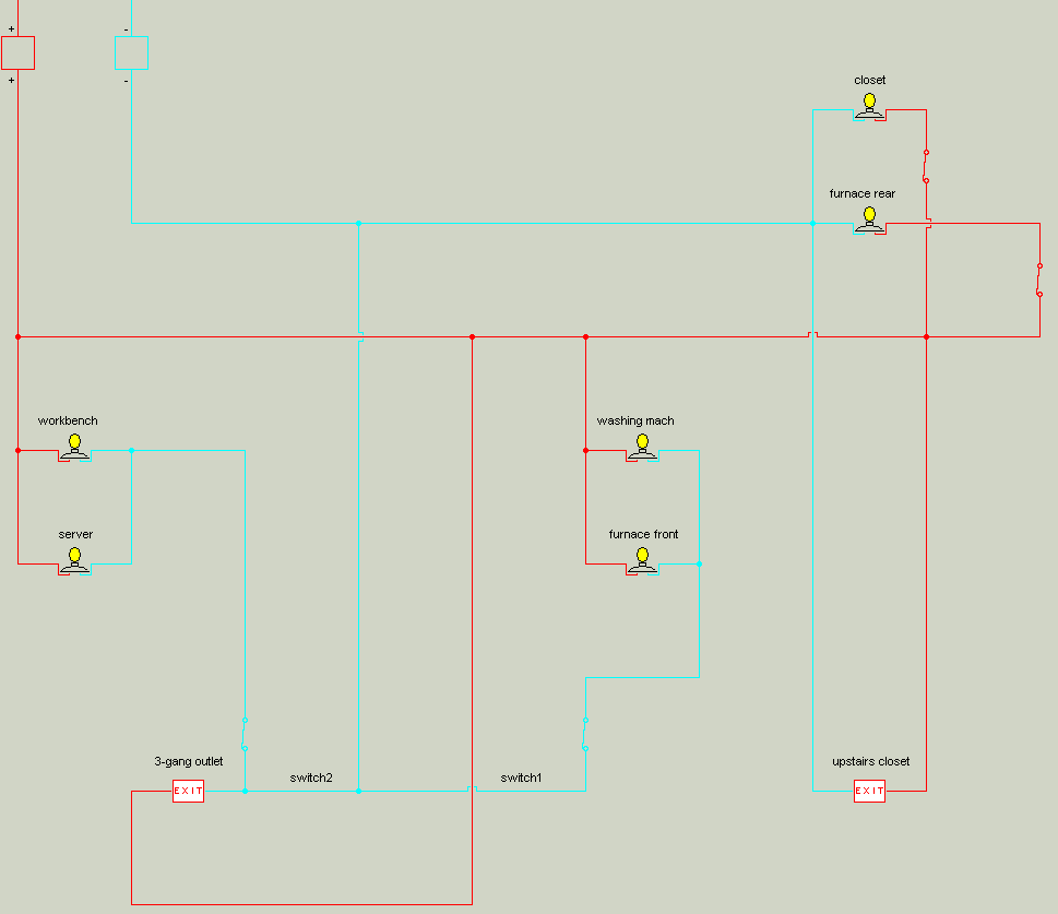
Here’s an animated GIF of how the simulation looks through the program’s GUI (click on the image to see the animation, doesn’t seem to work in some browsers as resized):
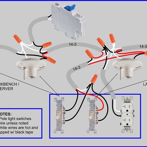
This “ladder diagram” can help as proof of concept, just to make sure you’re not forgetting something. But it would take me too long with this software to write (document) what I need to know to wire a bunch of switches, fixtures, receptacles, with 14-2 and 14-3 wires, and have it probably all work the first time. So I like to make photorealistic wiring diagrams complete with each wire and color represented (except grounds). It may take longer to make up front, but then it makes up time when I don’t have to think circuits through as I’m installing. I just do what I see.
In Which We Cast the Runes and Read the Entrails to Determine Receptacle Placement
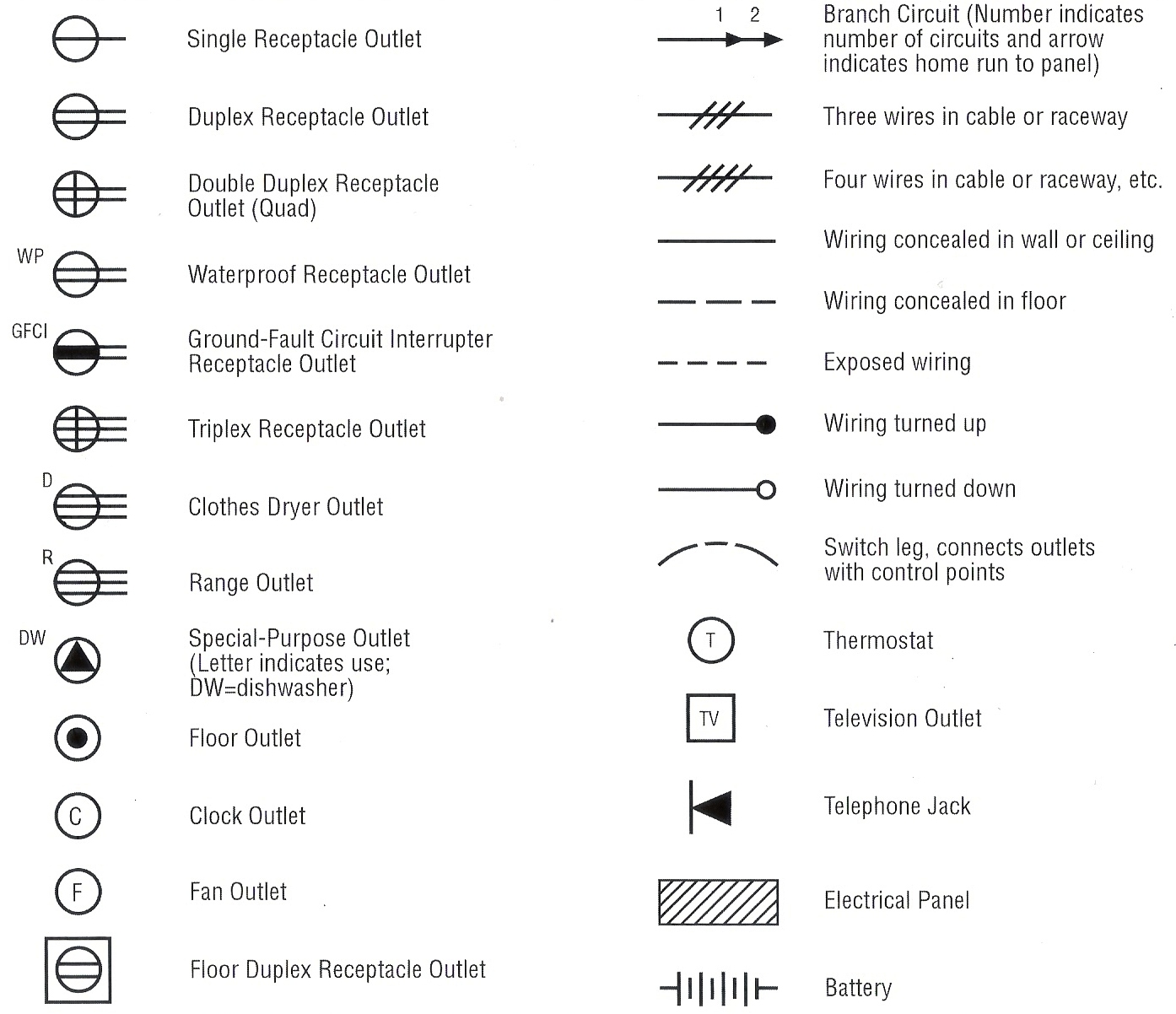
There’s another reason why, when it comes to a home wiring diagram, that I make infographic-style diagrams that anyone can easily understand (instead of schematics with industry-standard, yet layman-baffling symbology). First of all, I don’t really know the electrical symbols well enough; “…should I just do the little circle with 2 lines here or the one with 2 lines and a shaded part…?”
But aside from using blueprint symbols I’m not overly familiar with, I want anyone who’s an experienced electrician to understand—without ambiguity—what I’m planning on doing. Every white wire that needs to be taped black, every wire nut’s pigtails. Then, on a DIY forum, one of the helpful folks can tell me what I’m about to screw up before I do and tell me how to bring it up to code.
What’s Next, Food Supply Inspections?
IMO, they often make government regulations for very good reasons (or maybe they’re just lonely and want scores of constituents calling and screaming at them about “liberty”). I imagine one-too-many precious children burnt in their cribs after a homeowner decided rewiring the attic couldn’t be as hard as them fancy professional electricians make it out to be. And then someone calls their legislator after seeing the heartbreaking baby pictures on the evening news and says “Ya know: There Oughta Be A Law.” And then soon it is so (after a cynical display of partisan posturing and a backroom trading of horses upon the barrelhead of public safety).
Said homeowner must now perhaps pull a permit if he wants to wire his attic (if not grandfathered in nor living on an odd-numbered street in an even-numbered county), then have the work inspected and approved. That’s regulatory regime at work, saving lives. And I don’t want to be the guy who causes a safety issue in his family’s home just because he’s a frugal fool. You’re not saving any money if you burn the house down or screw up so bad you have to call an electrician anyway.

“I’ve always depended on the kindness of electricians”
I make the diagrams so obvious that even I can understand them, and then some experienced electricians who must just enjoy contributing to DIY forums will either be very nice and helpful in pointing out my mistakes, or very rude and helpful by explaining how if I don’t want to wire like a moron, I should do it how they say. Either way, someone will usually pipe up and claim that if I do such and so, it will be compliant with NEC-2011. And That’s what I want to do.

Diagram!
This diagram was created using the program “Xara Designer Pro.” I found the component images on Google Images and saved them as PNGs so they could have transparency, then used GIMP to delete backgrounds and crop.

And after it was revised a few times because of electrician feedback, and finalized, I decided to make a lighter shaded black and white version because I hate printing in color unless absolutely necessary. I’m a grayscale type a guy.

Aren’t computers neat? Makes you wonder how cavemen wired their homes.