A “Cheat Sheet” on File Structure for building Whole Machine CAD files
Until I stripped the infographic back down to a narrower scope, I couldn’t tell if this was a mess or if I’d successfully loaded a lot of pertinent, absorbable reference material onto one letter-sized sheet of paper.
Open the final version PDF here: REFERENCE SHEET – STABLE WHOLE MACHINE CAD FILE STRUCTURE FOR PRODUCTION
Catering to a Limited Audience
Some of the information is specific to a custom program I use that exports CAD BOMs as XML files, & drawings as PDFs, from the PDM DataBase service. It then imports that Product Data into the ERP to update ERP BOMs, and attach PDFs to PN records, which will then print out with Production Order packet documentation. So probably ignore tips regarding the specifics of an obscure product data management system I use…
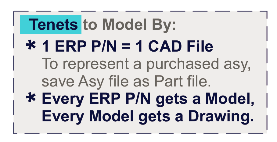
There may be some style differences between what you’re looking to do and what I do. One that comes to mind is how the system I use does not care if you have configurations for part or asy files, it’s going to look for the “Default” config. It pushes the product data for that config to the ERP to create or update entries and BOMs. In other words, for me, 1 CAD file = 1 ERP PN. So if you rely on using single CAD files for multiple PNs, ignore that “tenet”.
The Broader Strokes
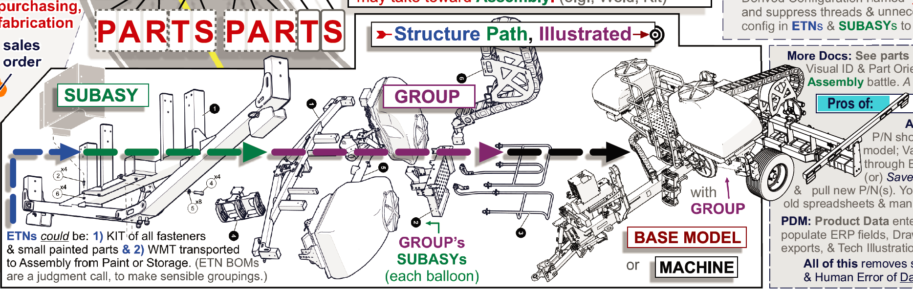
But there is some meat on that bone for those of us that aren’t me. The modeling and file structuring tips and Tree hierarchy are things I’ve worked out over years of experience trying to get CAD file BOMs (ETNs or E-BOMs) to be the same, when sensible, as how subassemblies and machines are actually assembled (M-BOMs)
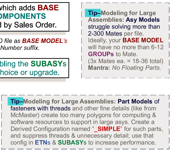
I have considerable experience with large CAD asy files (1,000+ part numbers)–which I’m attempting to distil and convey in the document. Experience through which I learned how to get large files to work, and work with reasonable performance and crash rates. This allows multiple teams to want to work from such a file, simultaneously, instead of it just being an unstable albatross that’s more trouble to open than it’s worth.
Basically, this acquired knowledge boils down to years of figuring out techniques to systematically reduce the amount of unnecessary Polygons (like screw threads), and Mates in top lev files (keep mates in any asy below 200 count), while still having the structures of CAD subasys represent how a machine is truly, efficiently assembled.
This can create a Master Document; for other stakeholders to understand a machine, and create vital documentation from to serve other clients in the production environment. From Fabrication & Piece Part & Assembly prints and instructions, to Manuals and Parts Catalogs for Product Support, to Renderings and other marketing collateral, to FEA and Testing reports…. Being able to craft large CAD machines in the face of their seeming will against being made can serve a lot of Enterprise.
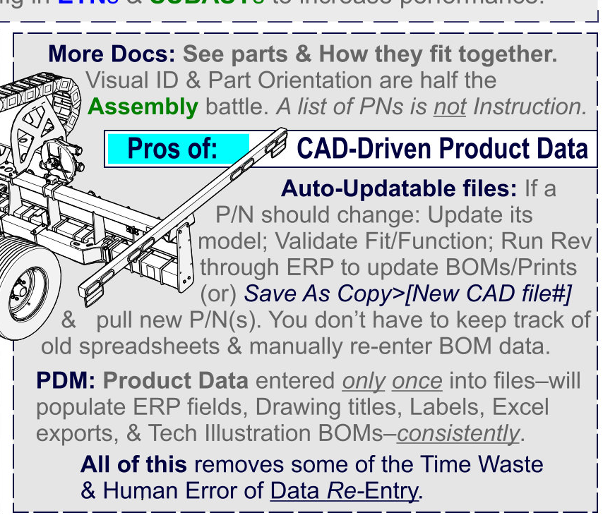
Single-Entry Product Data
And those same thoughtfully structured CAD subasys can also be used to push single-entry product data to the ERP; have new PNs and BOMs made (or old PNs updated).
What I mean by “single-entry product data” is data points you have to enter only once. In this case, enter the data up front, at the Ideation or Design phase of the product development cycle, into the CAD file’s User Interface (hopefully your CAD Platform Administrator has set up a nice Data Card or dropdown menu).
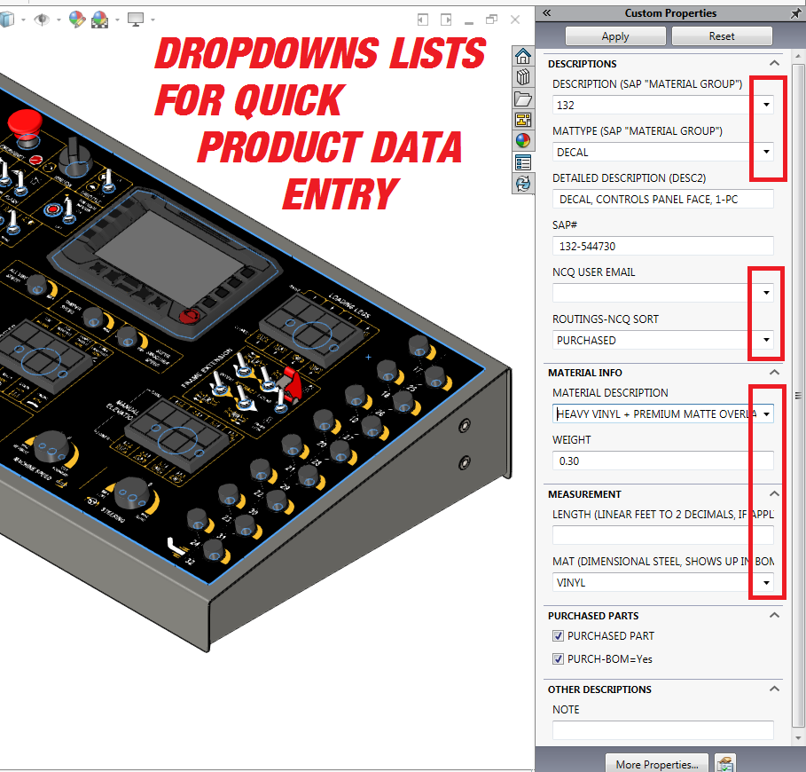
Then these data points (e.g., the part description or part type or raw mat PN, etc.) can be pushed to the ERP to create a new Part Number entry with that part description and part type, etc. You only had to type it ONCE.
Depending on system setup–which data points are mapped from CAD Platform to which data points in the ERP Platform–no one has to re-enter all those pieces of info from a spreadsheet or report. Even copy-pastes from a BOM export to other platforms can result in too much time and too many errors (transposed rows, not all the old rows deleted on an update, etc.)
Anytime you can reduce the number of data-entry events for the same data point–usually by programs that allow platforms to communicate or import data–the better; better for reducing human error and the entropy of info records being updated in some platforms but not others.
CAD-Driven Production
Well, Actually…
That’s a bit of a misnomer, as in my opinion, managers of a factory with a correctly-tuned ERP platform will want THAT to drive production. Essentially, you input a machine’s sales order in the front-end, and the ERP tool starts spitting out all the purchase requirements and production orders and pick orders and CAD prints and instruction documents and invoices on the back-end, and that’s Livin’ the Production Dream. BUT, getting there requires staggering amounts of data entry and that means there are HUGE opportunities for the product data that’s already been created and validated in the CAD platform to just transfer to the ERP and DRIVE Part Number creation & BOM structure.
Many of the data points and documents–that again, HAVE ALREADY BEEN CREATED, usually at the expenditure of great time, effort, and financial resources–can transfer to the ERP from CAD, and have CAD drive the data point creation that Design & Engineering should already know (descriptions, purch or fab?, material, weight, dimensions, visuals, instructions, etc.). In other words, CAD drives PN info record creation, and PNs are what a factory produces and sells.
CAD BOM Structure for Driving ERP
But for CAD to drive what the ERP tool tells everyone to buy, make, and locate; in a way that creates a value add of streamlining and reducing cost, CAD BOMs need to be set up in ways representative of how they’ll actually be made, which is how they’ll be “consumed” in ERP.
For example, If it makes sense to kit the nuts and bolts for a subassembly, then make a CAD file that is just an assembly’s nuts and bolts. Then push it to ERP to auto-create the PN entry and ERP BOM (single-point data entry: in the CAD platform, product data is entered in dropdown lists, and the asy file’s BOM transfers to the ERP). Then a production order can generate from ERP to ask someone to put the kit together and send it along to Assembly in a box, grouped with the production order picklist and CAD drawing that auto-printed at the Routed Work Center’s terminal.
Documentation: It’s Easier this way
Speaking of making simple Assembly CAD Drawings (a nut & bolt kit for a subasy should be a simple BOM), it should be as easy as:
- hitting a Hot Key to Make Drawing From File,
- choosing a drawing template that will prefill 3rd angle projection views (which can be deleted or changed to suit),
- hitting a Hot Key to insert the BOM table, and
- hitting a Hot Key to Auto-balloon the ISO view of the model.
- Slap your initials and a date on that bad boy and hit save.
That took 1 minute. Why do some people complain about modeling tasks?… Easier than entering BOMs into spreadsheets… Or at least the result is for everyone else when they have better documentation, including visuals. Picking parts from a list of tiny-printed part numbers with vague descriptions like “screw” is NOT HELPFUL, and really just makes the process take longer than visualized documentation. And when the Parts Picker has a BOM’d print in front of them, they can notice any discrepancies between ERP picklist and CAD drawing BOM table–It’s good to have checks on parts consumption, it reduces the amounts of incorrect parts getting sourced (or not getting the correct ones).
The Tree of LIFE… er, Stable Large Assembly CAD File Structure for Production Support
This PDF is the essence of that system; of CAD-Driven Production, and modeling so that the documentation that supports the most orderly purchasing, fabrication, assembly, testing, selling, & servicing of products is easier to create. If it’s confusing, let me know, I’m interested in infographics and pictograms and other graphical devices that convey a lot of knowledge in a little space, and how to make them effective.
Reader’s Note:
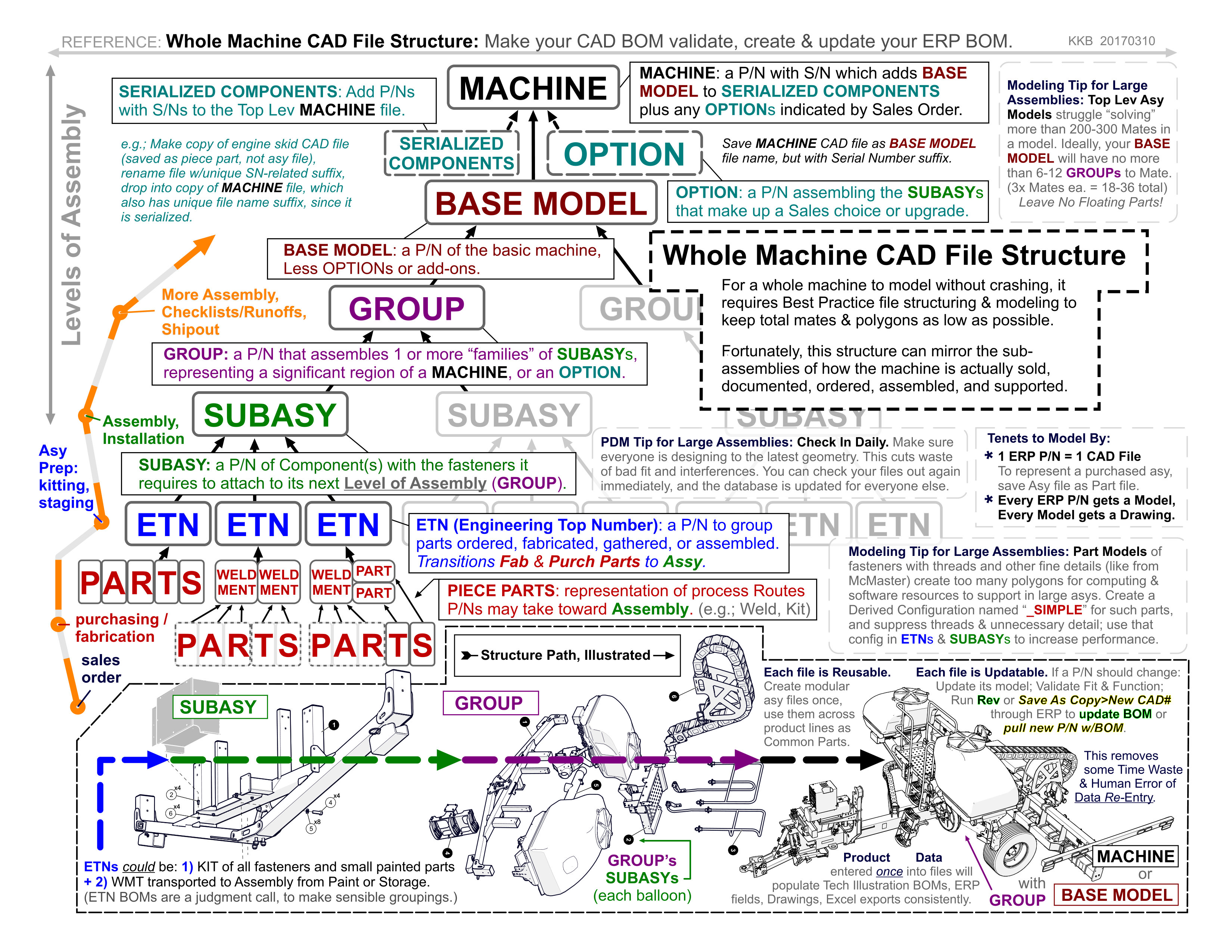
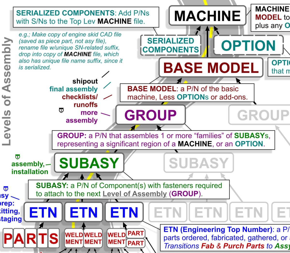
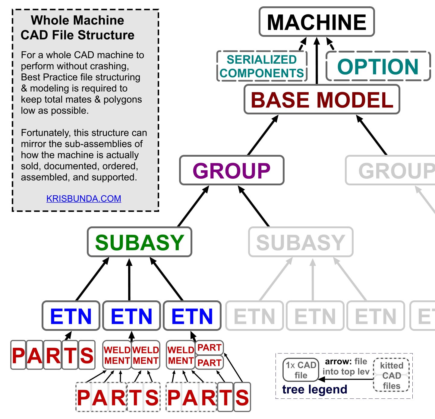
If the Tree chart is not clear, which I should update if not since it’s the crux of the graphic, realize:
- Each gray-outlined box is a CAD FILE (either Part or Asy type), and
- The arrows pointing up from each gray-outlined box to the next means THAT FILE has been ADDED TO the file at the tip of the arrow.
- In other words: a MACHINE file will contain in its “design tree” a BASE MODEL file PLUS any OPTION files and any SERIALIZED COMPONENTS files.
Infographic Evolution:
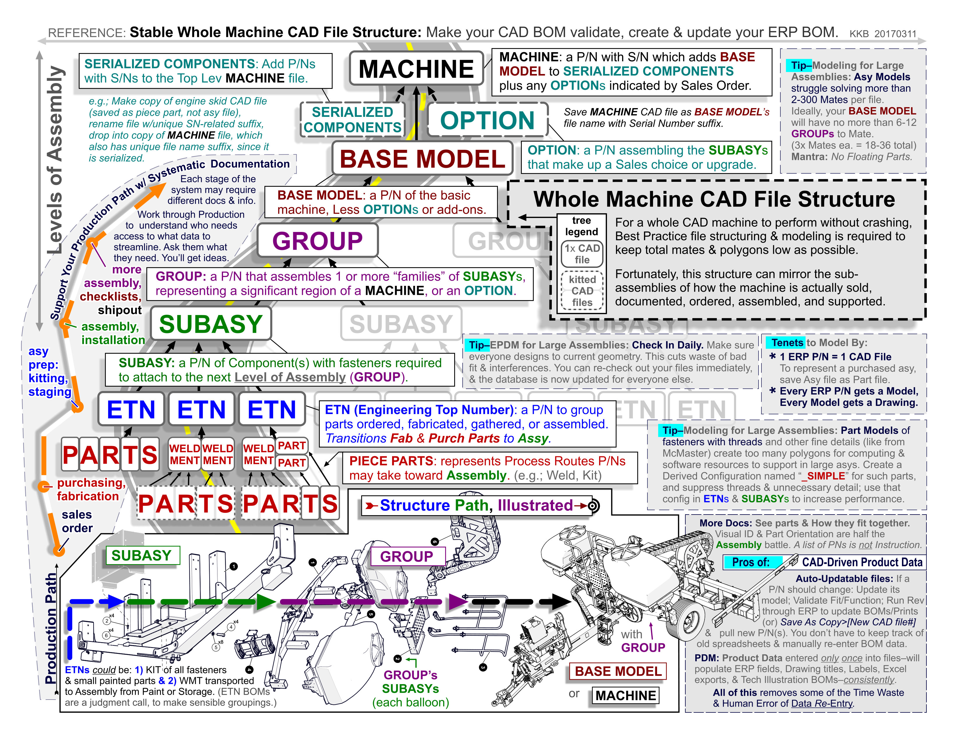
See how I wrestled with cramming all the vignettes and “important” parts onto the page before finally deciding Less is More. I threw a bunch of the sections out in favor of focusing on the Tree and a few must-do tips for reducing top lev Mates & Polygons, 2 of the biggest culprits in crashing Large Asys CAD files.
If an infographic is just a wall of 8pt print, it’s probably not presenting a narrative of helpful knowledge, but instead just an imposing cipher.
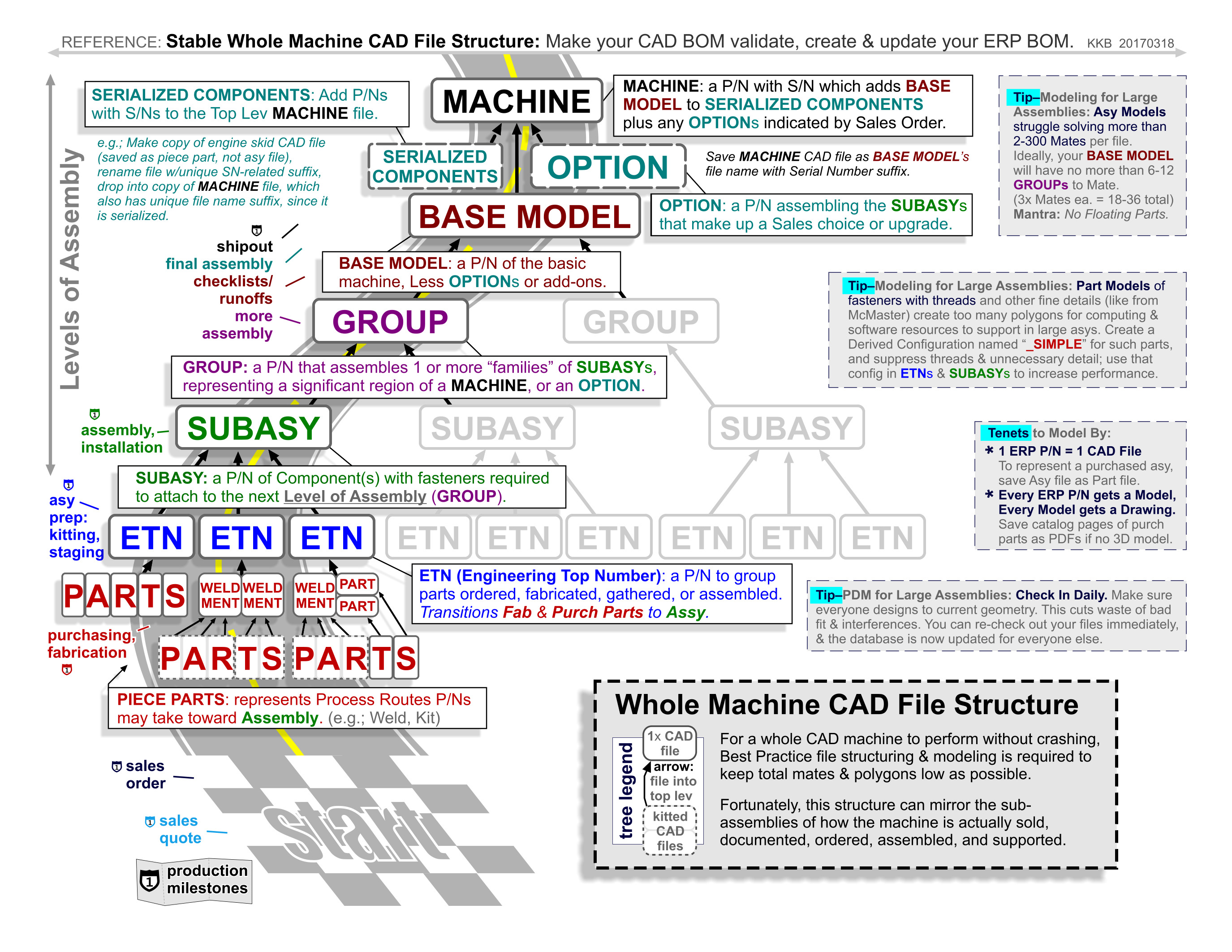
Notice the last version has more white space, and room for the “parallel path through CAD file structure & Production Milestones” theme to be fleshed out.
Here’s that PDF link again: REFERENCE SHEET – STABLE WHOLE MACHINE CAD FILE STRUCTURE FOR PRODUCTION