I felt like this whole balcony extravaganza was getting a little too hysterically long, so I split it into a Design post and an FEA post. If you’re seeing this post first, but want to see The Origin Story of the world famous balcony series, click below:
♦ Curved (Rolled Sheet Steel) Decorative Balcony Designs that Mimic Wrought Iron Fabrication (Go to the balcony design post)
FEA Simulation
Here’s the meat & potatoes section. I don’t know why I said that. Actually, this is some screenshots and explanations of how I set up a simulation scenario, complete with fasteners, external fixtures, and mass loading. I wanted to safety test this thing to make sure you could park a subcompact car on it before someone’s grandchildren stand on it.
Simulation Problem Setup
Models:
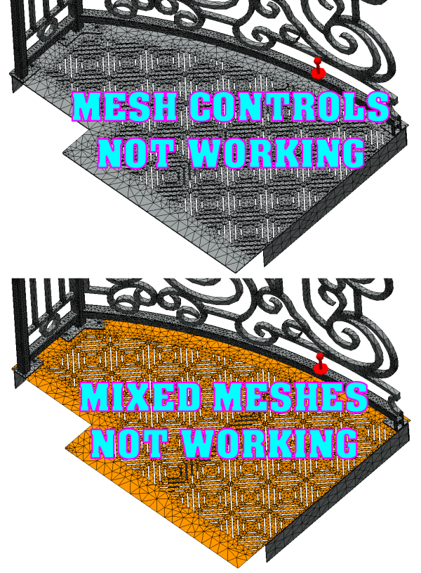
To set this up, at first I kept trying to use the assembly file. This means I tried to mesh all the solid parts of the assembly. Then I tried to create shells and beams and solids and super-fine mesh controls and any and every combination of mixed mesh ever conceived of. There were always problems! I couldn’t get a believable result, if I could complete a solve at all!
Sometimes the road to simplicity is a complicated maze.
And it was all because I really wanted to get that grate deck top to mesh with all the slots in it, because I’m thinking with all that material missing, it will affect the strength, stiffness, and make it act more like a spring than a slab. But it just didn’t want to work, whatever I tried.

So finally, after wasting way too much time on this, I just created single-body part versions of the 4 bolt-together subassembly weldments (Deck, Front Rail, Side Rail LH, Side Rail RH – and I really didn’t need one of the sides since I cut the railing in half for symmetrical solving). This means each subassembly has a configuration where everything is suppressed except the single-body part file version of itself. And I extruded a boss through the grate on the deck to make it solid.

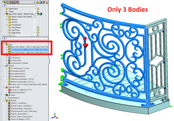
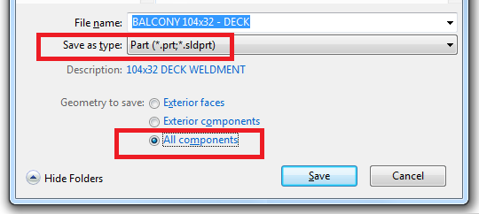
This means there are essentially only 3 bodies in this simulation (after symmetrical cut out completely removes a side rail). I did this by saving the assembly files (*.SLDASM) out to part files (*.SLDPRT) and making sure to choose the little checkbox in the Save As dialog that saves all surfaces and bodies (“All components”). Otherwise, I was getting broken surfaces.

Then I had to do some massaging, adding in bosses, using the “Surface” tab to thicken and merge faces, using the “Direct Editing” tab’s “Combine Bodies” to get bodies to go together into one. This can also be a good diagnostic tool – if you can’t get bodies to combine, they must not be properly merged somewhere. So you’ll need to find a way to make a feature that connects the body to another. Of course, this is all for simplicity’s sake, so hopefully what you’re doing isn’t too complicated or time-consuming. Unfortunately, sometimes the road to simplicity is a complicated maze.
Global Contacts and Contact Sets
First, Let’s Show What Not To Do (Apparently Contact Sets don’t always override Global Contacts…)
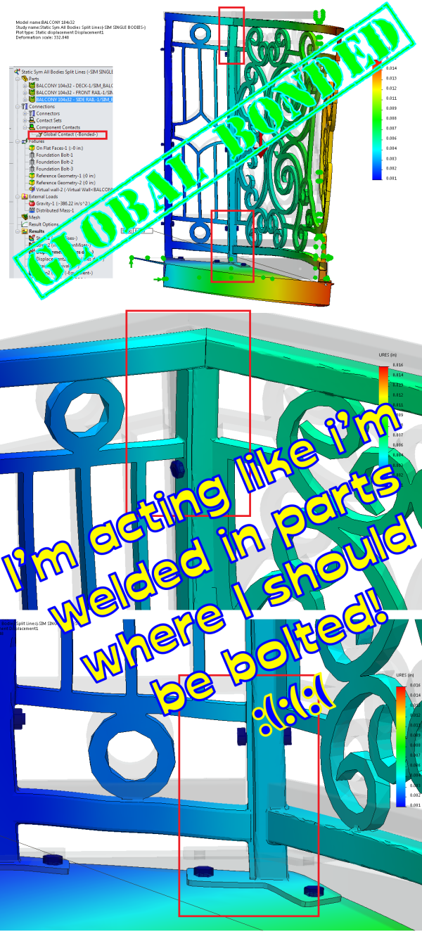
I previously made the mistake of leaving on “Global Contact: Bonded” in this study. I didn’t think it would matter, as there are No Penetration contact sets in the study for all the faces that should have it, and contact sets are supposed to outrank global contacts. But it was obvious when looking at the displacement plot results that this rule was not being observed.
I must admit, I have had trouble getting the solver to exhibit the bonded behavior again to verify it. But it comes out with the following choices: Selected for non-touching faces, within 6mm of each other, to be bonded as incompatible mesh. Not sure why the contact sets didn’t supersede this errant global bonded contact, but you can see what the differences are below.


Here’s with the Global contact on, it makes some parts that should be just bolted together (No Penetration) act as if welded together.

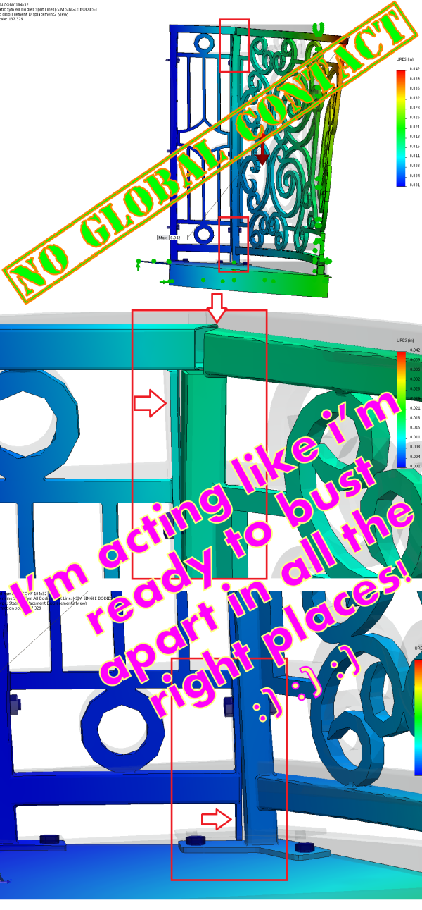
Here’s with the Global Bonded Contact suppressed (and proper No Penetration contact sets in place):

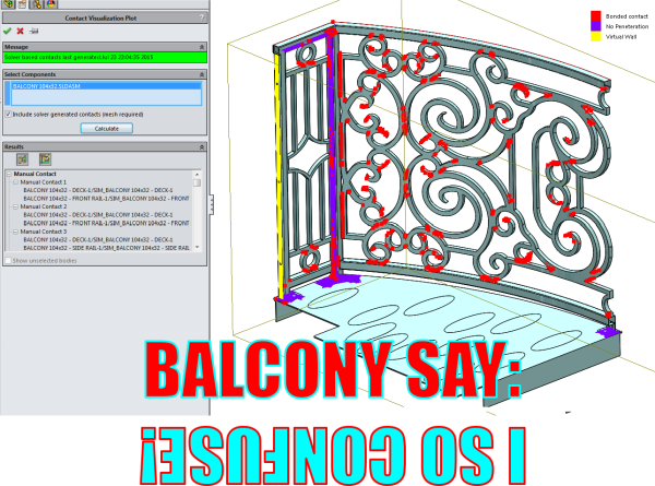
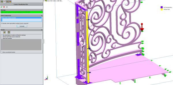
Here’s the Contact Visualization Plot, to show what is happening when the Global Bonded contact is on. The solver thinks, in some areas, the parts are both bonded and not bonded. No wonder it would take so long for the problem to start solving when this was happening. Also, notice all the little red spots on the scrolls on the front rail. I think that’s the “6mm” non-touching faces option trying to weld together all these parts to themselves. This is why the Contact Visualization Plot tool can be very helpful in telling you what SW Simulation thinks the relationships are between parts.

Hopefully this helps as a “What Not To Do with Simulation Contacts” lesson.
No Penetration Contact Sets & Contact Visualization Plot
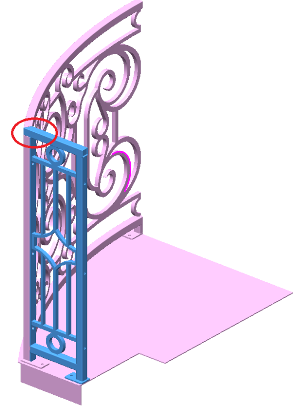
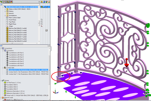
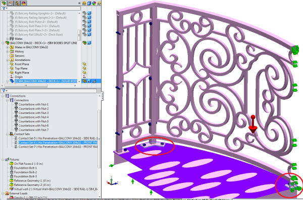
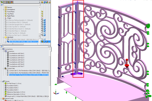
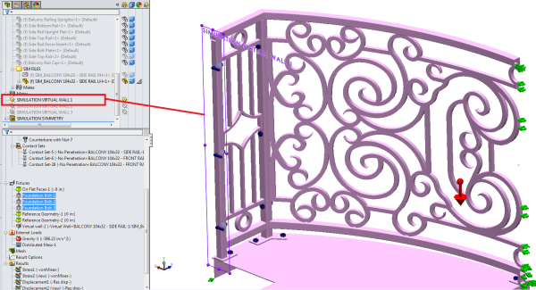
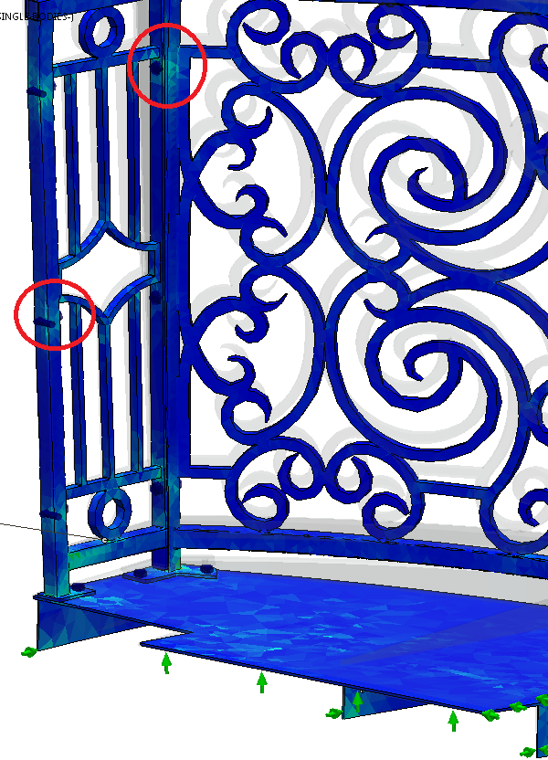
The relationships between the 3 weldments are explained to the simulation software by clicking the interfaces (circled in red below) and marking them as “No Penetration” contact sets. No Penetration is appropriate because they are bolt-together pieces, and they should deform as such under stress, instead of acting as if they’re glued or welded.
External Loads
- Gravity was applied to the top plane to account for the weight of the balcony.
- The default for gravity was used. I have not yet tested for residents of Jupiter.
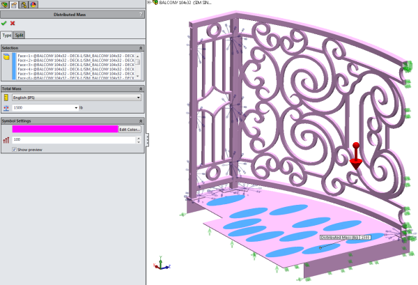
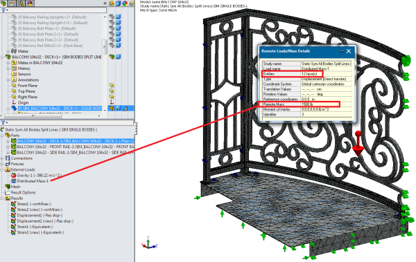
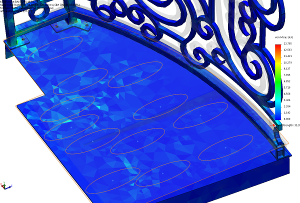
- 1500 lbs of distributed mass was applied to the “footstep” areas (created with a sketch and then converted to split lines).
- There are 6 pairs of “feet” on the balcony half. I want to simulate that somehow, on this 20 sq ft balcony, twelve 300-pound guests have shown their utter contempt for the laws of physics and shoehorned themselves onto the deck.
- Since this is a 1/2 symmetry setup, I used 1,500 lbs for weight, because I want to apply 3,000 lbs to the entire balcony.
- Notice how the mesh elements concentrate around the weight-loaded shoe prints.
Fixtures
In addition to the fasteners used, there are some fixture features made to recreate environmental conditions.
All fixtures highlighted in the feature tree will make its arrows appear light blue in the screenshots below.
- Side of Building: Though this fixture is named “On Flat Faces” in the tree, it was changed later to “Reference Geometry”, but the tree feature did not rename itself. This fixture is supposed to be the side of the building. If the weight on top of the deck leads to enough deformation, the corners of these ribs will dig into the exterior materials.
- I didn’t use a virtual wall because the solver seemed to be glitchy when I used more than one parallel virtual walls.


- Makeshift Symmetry Fixture: This fixture will not allow all the bisected faces that resulted when I cut the assembly in half to move toward where the missing half would be. This does the same thing that a “Symmetry Fixture” would do — but sometimes the symmetry fixture won’t work because for some reason SW Simulation doesn’t think you have perfectly cut your geometry in half (or fourths or eighths, I think… I don’t usually have radially symmetrical problems.)
- If you’re trying to use a makeshift symmetry fixture with shells or mixed mesh with shells, you’ll need to grab shell edges instead of faces. You’ll still want to set translation normal to the face (or selected plane) to zero, but you’ll probably also want to set the rotational movement to zero in the other two directions that weren’t normal-to.


- Door Threshold Fixture: The plan is for this edge, and maybe a little more surface area around there, to sit on the door threshold. Thresholds are usually angled downward to shed rain, yet the balcony deck will be level with the world, so it’s likely that only the edge will rest on the door’s threshold.


- Virtual Wall Fixture: I don’t understand why it’s necessary to set up a virtual wall fixture IN ADDITION TO a foundation bolt fixture. I would think it would be assumed that the object will not move through a foundation. But I’ve read several places that in static studies, which allows you to use foundation bolts, you must also set up a virtual wall so the solver understands that the object is up against something.


- Foundation Bolts Fixtures: These are the only thing holding the balcony assembly – hundreds of pounds of steel – to the side of the building. But they’re supposed to approximate 1/2″or M12 lag bolts drilled at least 4″ to 5″ into 2″ x 6″ wood wall studs.
- FYI Tip: You can right-click on a bolt in the tree and copy it, then paste it by right-clicking on “Fixtures” and clicking paste. You’ll have to re-choose the edge or cylindrical faces for the other bolt holes, but all the other options you chose should be there. Nice time saver.

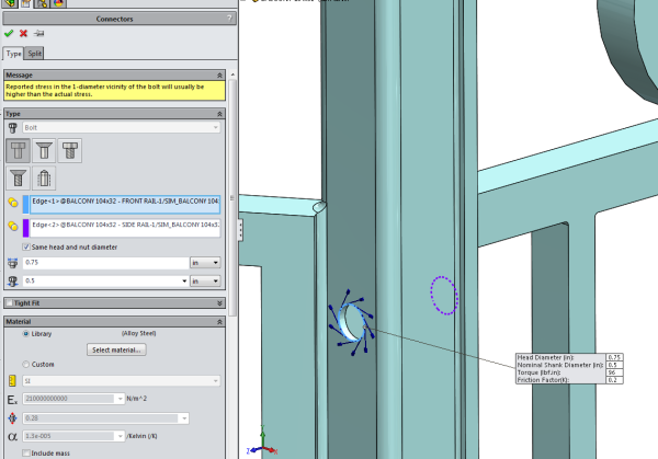
- Connector Bolts with Nuts (Simulation describes as “Counterbore” bolt with nut, but it is not c-bored).
- I changed the shank diameter size to 1/2″ and looked up the head size on a bolt chart.
- I used the default “Alloy Steel” for the fastener material, with its default SolidWorks material attributes.
- I used a bolt torque chart to determine the amount of ft/lbs per square inch for a bolt this size made to Grade 8 standards.
- I left the friction ratio as default.

Simulation Results
Displacement Plot
Although SolidWorks Simulation may present these plots in very exaggerated scales of deformation, you can see I set the units to inches, the chart options to 3 decimal places, and the Max callout shows that the most deflection of the assembly under load is less than a sixteenth of an inch. Frankly, I find it hard to believe if you put 3,000 lbs on this thing, there’d be so little movement, but it’s also not as if there’s much leverage involved. This deck hugs the side of the building pretty closely.


Stress Plot – Von Mises
- The stress plot shows that most areas of the assembly are not stressed. I would say, looking at this, that there are really no areas or joints that demand adding more gussetry or material thickness to stiffen it.
- According to this stress plot, the maximally stressed element isn’t even close to the yield point of the material specified (from SW materials database, “Plain Carbon Steel,” in this case).


Some Examples of Visual Cues in Simulation Stress Plots, and What They Say about Design & the Study
- Stress concentrations around bolt fasteners IN GENERAL.
- This visual cue tells that the bolts and nuts are actually doing something, and the simulation problem was probably set up correctly in this respect. As loads are applied to the object that makes it try to force itself apart from its various pieces, you can see stresses build up around the bolt holes as the fasteners strain to clamp the pieces together. If the study had been set up incorrectly, to bond all the parts together as if each face was perfectly glued, you wouldn’t see stress concentrations as much around bolt holes. It would be more evenly shown across mating faces and edges.

- Stress concentrations around SPECIFIC bolt fasteners.
- Check all parts’ bolt hole stress concentrations. Sometimes a contact set between 2 parts’ interface appears to exhibit a true stress relationship, but then another pair of parts are interacting apparently falsely at their connection points. Check thoroughly for cues, and use the Contact Visualization Plot tool.
- Just because a bolt hole doesn’t exhibit much stress doesn’t mean the study setup is flawed. It may be that the particular loads do not affect some of the connections as much as others. But lookout for discrepancies, and make your decisions on what they mean.

- Stress Is Where You Find It
- Concentrating the loads across sets of footprints doesn’t seem to matter. Probably because the steel plate is .188″ thick, and it doesn’t have all the material for grating removed. It’s a coarse mesh, too.
- Some of the problem areas you thought you’d find may not materialize, and some patterns may be a surprise.

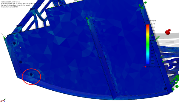
- FEA-Inspired Design Changes
- Stress Plot Visual Cues – See here that the weight is pushing the deck down and the corner of these ribs would be forced into the wall of the building due to a hinge effect from other constraints.
- Here’s an example of FEA simulation driving design changes:
- I think I would do better to add at least a .25″ fillet to the corners of these ribs so if they are installed as to be so close to the building, and are then forced into the siding of said building, that they may not dig into the material with such concentrated forces as at a sharp edge. I would think it’s bad design to see a product installed that unintentionally and needlessly damages the finish of its substrate.
- Another idea would be to continue the skirting around the back of the deck, which would take the interface between the rib ends and building siding out of the equation completely, and may or may not look better aesthetically.


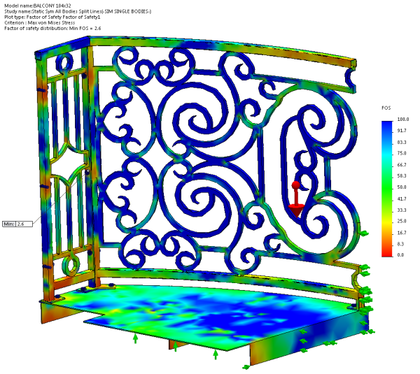
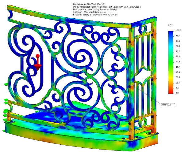
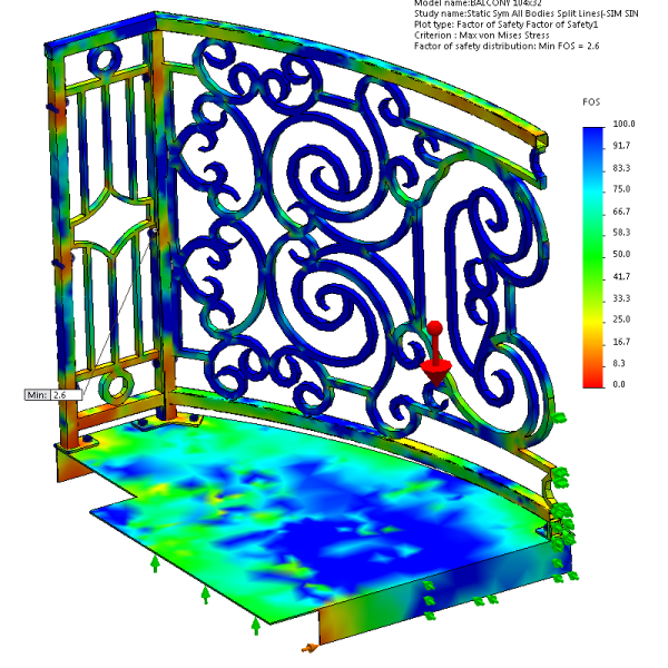
Factor Of Safety Plot
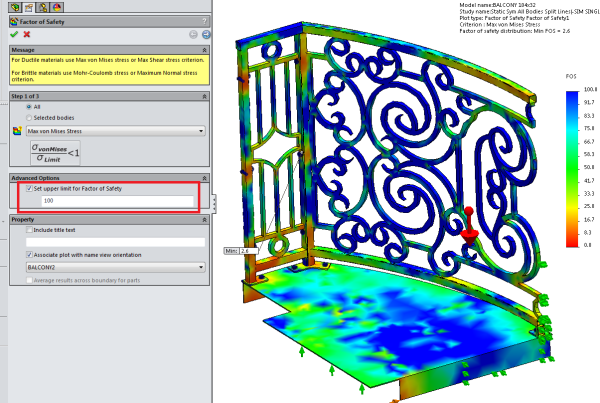
FOS Wizard:
- Step one:
- I chose Max Von Mises Stress since it’s steel,
- and I came back later and changed the upper limit for FOS from 3 to 100 to create more visual demonstration and resolution in the plot. (2.6 was called out for Min, and an upper limit of 3 therefore looked pretty blue all over.)
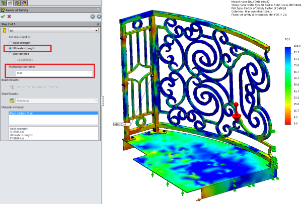
- Step two:
- I prefer to use ultimate strength,
- and to be ridiculously zealous, I used 3 times the breaking point of the material, or a Multiplication factor of 0.33.
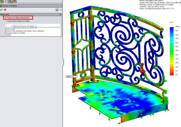
- Step three:
- I chose to view a Factor of safety distribution for the plot, as there proved to be few areas below a factor of safety of 3, and the shown Min of 2.6 is very acceptable.