I don’t have a clue.
I’m no electrician, and trying to get home wiring circuits to work without pulling any more wire than necessary can leave me feeling way dumber than a series of 2- and 3-wire twisted pairs should.
But I like to plan things out in advance and build according to plan. I hate to spend time pulling wire and making connections to then get to the moment of truth when you flip the breaker back on and flip your first light switch only to have it not work. And then it turns into a trial-and-error troubleshoot. No thank you. In this day and age, we ought to be able to set up our virtual circuits and see if the light switches are going to work before a single wire is pulled. And that’s what I did this time.

In Need of Some Simulation
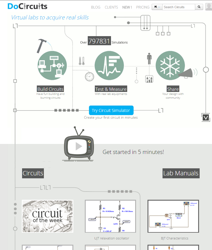
A home wiring circuit simulator is surprisingly difficult to find – at least a free (or trial) version. There’re quite a few simulators for electronics or microcontroller builders, but when it comes to just plain old 120V home light switching simulators, I’m either not Googling correctly or they’re not out there. I tried make do with a couple different virtual circuit labs, but I’m no Electrical Engineer, and even though I understand some of the parallels (switches are switches/indicator lights are light bulbs, right?), none of them seem to have real-time switching. I would build a circuit, but then have to run a simulation and add in measuring devices to see if my light bulbs turned on. I couldn’t just click a switch to turn a bulb off/on, it had to be set up as a timed event and simulated. It wasn’t working for me.
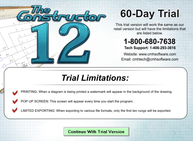
So I tried The Constructor software for wire circuit simulation, which is basically the same thing, but has some more AC single-phase power options to simulate, has a mode that you can switch in real time, and the vendor offers a free trial for 60 days.
You can see in this screenshot that I used “EXIT” signs for my outlets because the outlet icons I found didn’t seem to be able to wire up to the grid nor indicate if they were live. So I used a different sort of indicator light instead as stand in. Could be I just don’t know how to use the program too.
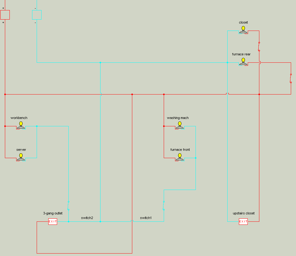
Here’s an animated GIF of how the simulation looks through the program’s GUI (click on the image to see the animation, doesn’t seem to work in some browsers as resized):
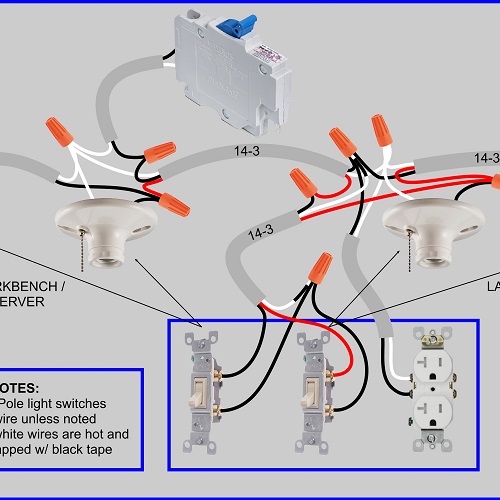
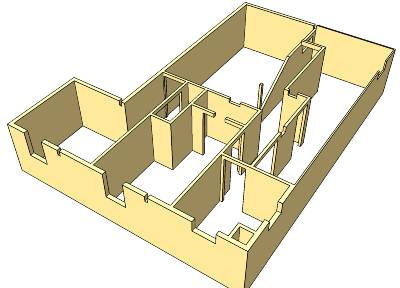
This “ladder diagram” can help as proof of concept, just to make sure you’re not forgetting something. But it would take me too long with this software to write (document) what I need to know to wire a bunch of switches, fixtures, receptacles, with 14-2 and 14-3 wires, and have it probably all work the first time. So I like to make photorealistic wiring diagrams complete with each wire and color represented (except grounds). It may take longer to make up front, but then it makes up time when I don’t have to think circuits through as I’m installing. I just do what I see.


Mark
So, after all this, did you get a working home wiring simulator package? I, too, have been looking for such a program. I had one back in the early 1990’s that allowed a person to hook the wires together, throw the switch and see what happened. I used to get dim lights until I moved the connections. It was on a 5.25″ floppy and I can’t find it anymore.
Kris Bunda
Hi Mark,
Yes, I like “The Constructor” software well enough, although I still think there’s a market out there for a software package that would allow for intuitive use of building a home (or commercial/public building) wiring diagram, and see if all the light switches work and appliances get juice.
So what I’m saying is: The Constructor is surely great for cooking up “ladder diagrams,” but I’d rather have a program that I can look down at a 2D floor plan and run little spline lines to little fixture boxes and then know if they’re going to work as a valid circuit. That’s more how my brain want to process and plan these projects.
I’m sure something like this exists (or multiple versions from multiple vendors), but I certainly didn’t find a free trial version when I was looking. If it doesn’t exist, why not? Is it because electricians are a licensed profession, and they’re supposed to do this work and they don’t need no stinking software?
Otherwise I would think a market exists for serious DIYers and maybe even just some builders whose electricians want to plan out and print simulation-verified documentation ahead of time, but maybe that’s a misunderstanding of how these things are best done.
Tyler D.
sierra home architect or sierra complete home used to have a program add on that was a wiring simulator, it was perfect, you described exactly what it does, unfortunately i cant find my copy of the program, its pretty old, but it would be the Ideal program for you.
Kris Bunda
Thanks for the info Tyler. I saw a copy on Amazon for Windows95/98/2000. Seems like other people have tried to get their copies to work on newer Windows OSs. I wonder if that software company went out of business, or just decided to get out of that product line…
http://answers.microsoft.com/en-us/windows/forum/windows_7-windows_programs/running-sierra-home-architect-40-in-windows-7/07f582af-eb78-4c72-9dce-c5a58704de1e?auth=1
Tyler D.
In my move last month i found it! the Wiring program, it runs on Windows XP, I have a VM for that, If you want to, I can send you or anyone who wants a link with a ZIP file. This kind of tool should not be allowed to die.
Kris Bunda
If you don’t think the publisher is in the business of caring about it anymore, maybe you could share a link to a Google Drive / Dropbox / whatever here, that would be okay with me.
Nate E.
I’d definitely appreciate a link too 🙂
Nate E.
Glad to see I’m not just dumb/have poor google-fu and have had difficulty finding things for this exact same problem! Well, almost the exact same problem—the problem of needing a residential circuit designer/simulator at least, in my case because installing a few 3-way dimmers into a poorly-laid-out (but working) circuit devolved into half the lights, outlets and microwave(!) on the circuit only working depending on the configuration of various supposedly-unrelated switches. I pulled out every switch and half the lights so I could mapped every 2- and 3-wire in the circuit, but I feel like an idiot and I just can’t wire everything back together with all the various 3-ways working as they should. I’ll definitely check out Constructor.
Kris Bunda
Ha! That’s why I wrote something along the lines of “why should a twisted pair be so confusing?” I suppose with dimmers you have 3 wires, which further complicates things. I hope you get it figured out soon. Also hoping Constructor has dimmer switch simulation–I can’t remember much about it now. Good luck!
jchorman
If you have $52 Dollars I believe this is what you are looking for
http://interplaystore.com/products/residential-wiring-2011-nec-code
Kris Bunda
I remember this from back when I wrote this post. But it looks like now when I go to the link, there’s a “Free trial demo” link, so that might be worth a try. Thanks jchorman!
Ivan
I am a chartered Architect in the UK, engaged in a DIY build of my own, and I too can hardly believe a circuit simulator does not exist. I am working from a respected book on electrical installation, which is not very well written, trying to ensure everything is installed in accordance with the building regulations, and it would be great to able to hook everything up virtually first. For example – low voltage LED spotlights draw a higher current than incandescent bulbs. I learned this from the textbook, and I understand why (ohm’s law) – but damn, it took a long time to get there. What is the internet for, if not to speed this sort of process up?
Btw, for anyone thinking: what the heck is an architect doing, not knowing how to design a lighting circuit? The answer would be I can and do design layouts, daylight levels, switch types, etc etc… but the installation is designed by the electrician, who certifies it.
I would LOVE to issue a lighting diagram that tells the electrician what thickness of cable to use, what configurations, etc.. and I will get there someday.
Good luck all!
Kris Bunda
Thanks for your perspective Ivan!
I would hope Autodesk Revit electrical (or similar pro-grade BIM software) could simulate and fault the circuits of a wiring layout, but maybe that’s too granular for the software to handle? Maybe there’s just not the economics in this aspect of BIM software to support circuit simulation? (even though microcontroller simulators are widespread and free).
http://www.autodesk.com/products/revit-family/features/mep-engineering-and-fabrication/electrical-design-and-documentation