Comparing Multiple Studies’ Plots:
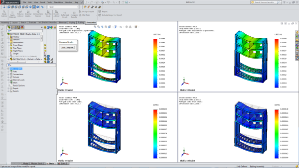
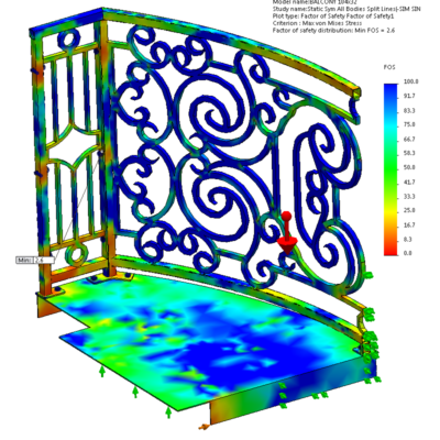
Here’s a screenshot of comparing 2 plots from the 2 different simulations and configurations. (I created “SIM1” and “SIM2” -titled configurations to remove parts that weren’t necessary, like the sign and the bat, and then to add-in the new parts). You can see the displacement and strain plots compared here:
SolidWorks Simulation “Design Insight”:
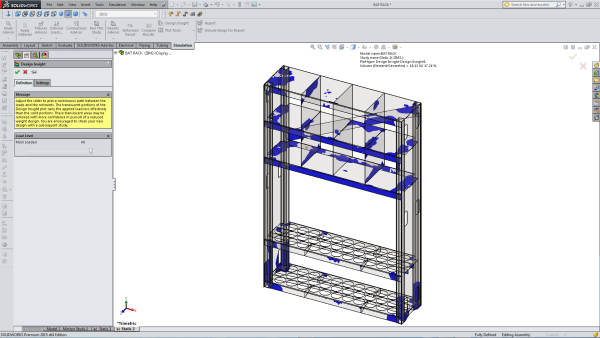
This is new to me, and I don’t know if I trust it yet (or trust that I’ve set up my simulation well enough on some parts to trust its feedback). But as I understand it, the blue areas are doing most of the work of upholding the loads I’ve placed on the model, but if I wanted to cut weight and material, I could feel much more confident doing it on the translucent areas. I can see this being a very handy tool.
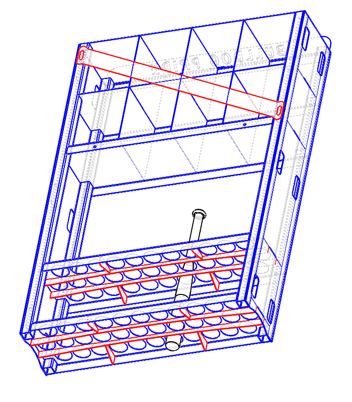
Design Changes
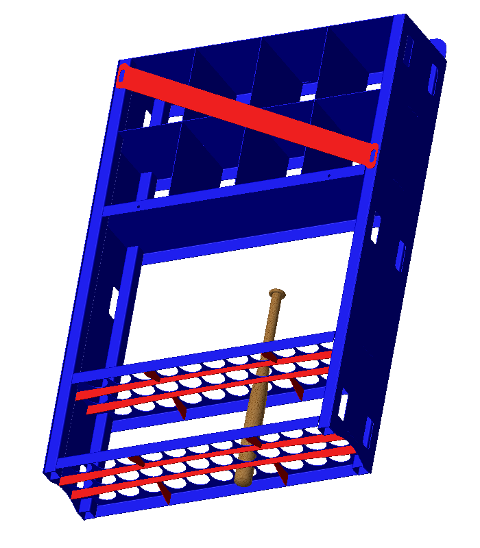
Here’s some screenshots of parts I made to reduce deflection, with the added parts in red (one is wire frame, one is just shaded, depending on what’s easiest to view).


Leave a Reply about how this blog changed your life.