Haste…
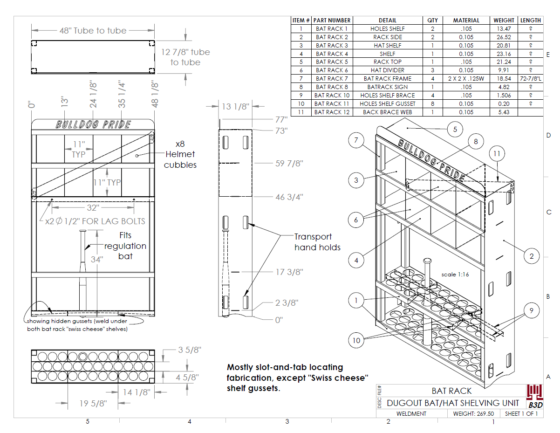
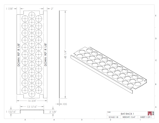
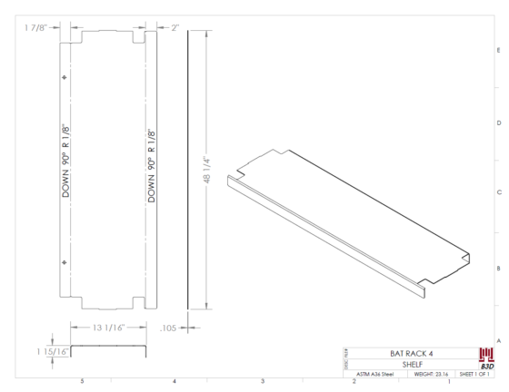
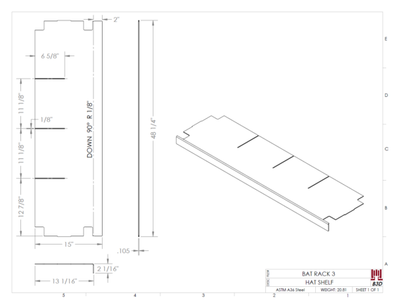
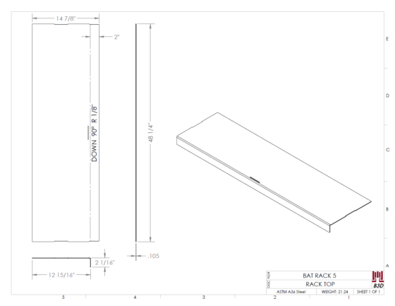
I designed this bat rack with helmet cubbies for a coworker’s little league team’s dugout. I rushed to get it done in a few hours using just a couple materials we knew we had plenty on hand (2×2 square tubing and 12ga sheet steel).
Features and work included:
- slot-and-tabbing for the welder to locate and fixture parts,
- lettered sign with stencils added to the text (for lasering),
- producing all bend, saw, & weldment fabrication prints,
- CNC file exports for the laser (DWGs).
2 CAD Thoughts:
When I came across this project a few years later, two thoughts occurred to me:
- This would’ve been a perfect SolidWorks “Weldment” multibody part file project.
- I didn’t start using this modeling style to any advantage until later, but it would’ve made the project go even faster I think.
- Although… Solidworks really needs to get their crap together on exporting formed sheet metal from “Weldment” part files. They work fine in the part file as plates with flat patterns, but save the bodies as external files and there’s trouble. I have to convert the Saved Body features into sheet metal again, and often the flat pattern is bad, especially for “rolled” bend parts.
- Sometimes I have to completely redo the part (this is because of how our ERP and nesting/press-brake software systems like to process parts. They don’t understand multibody *.sldprt files.)
- So…GET IT TOGETHER, SolidWorks. Make exporting configured bodies (having both default & SM_FLAT PATTERN) out of multibody parts into part files an easy process.
- I should see what happens to this thing in FEA simulation.
- I was pretty sure since I had cranked it out so quickly that I had overlooked some durability issues. Since this is outdoor sporting equipment, any weaknesses will have a greater likelihood of being exploited by young rammy athletes or angst-ridden vandalous youth than say, a curio cabinet in grandma’s dining room.
FEA Static Analysis
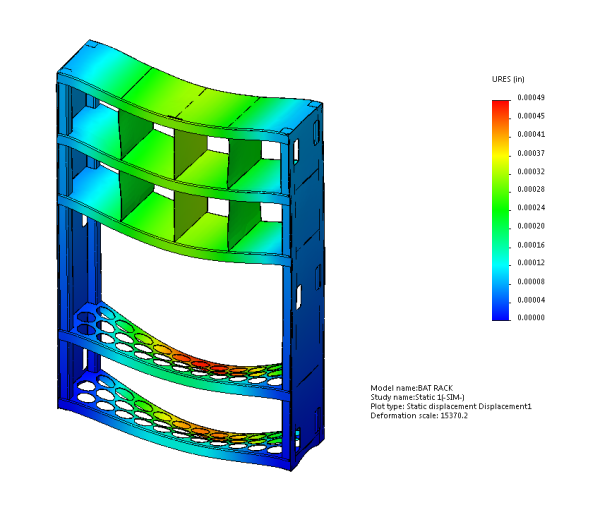
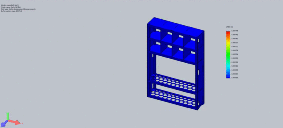
I put about 500 lbs of force distributed on the 5 shelves in total, and also put a moment load coming in at an angle against the side of the shelving unit, to pretend that someone leaned against it a little roughly or gave it a shoulder slam, but it didn’t seem to make a difference in the analysis.
Here’s the before simulation displacement plot:
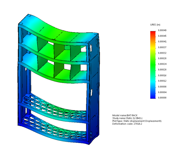
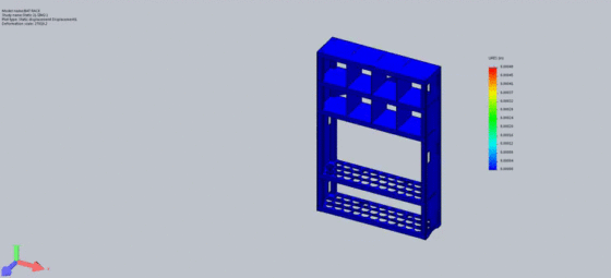
Here’s the after plot (after I made some ribs and a back cross brace for the shelf)
Conclusions:
Notice the bottom 2 shelves have been strengthened and stiffened especially from adding ribs under them. Also notice the cross brace webbing on the back isn’t really doing much and would probably just be added weight, material, lasered linear inches, weld time, and paintable surface area.
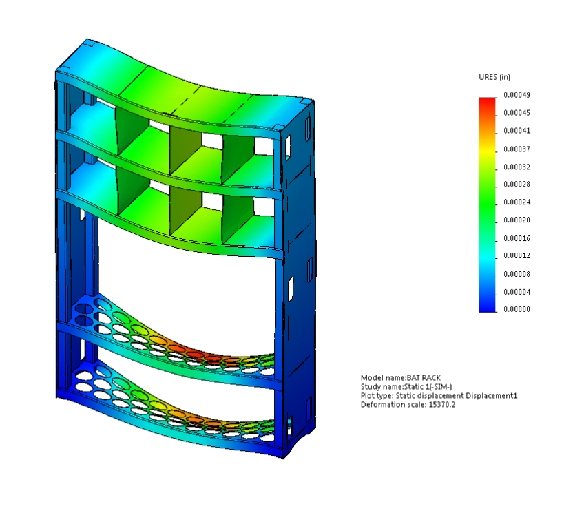
Animated GIF versions of Deformation Plots:
(Depending on your browser, you may have to click on the images until you can see the original to see it animate).



Leave a Reply about how this blog changed your life.