Some Examples of Visual Cues in Simulation Stress Plots, and What They Say about Design & the Study
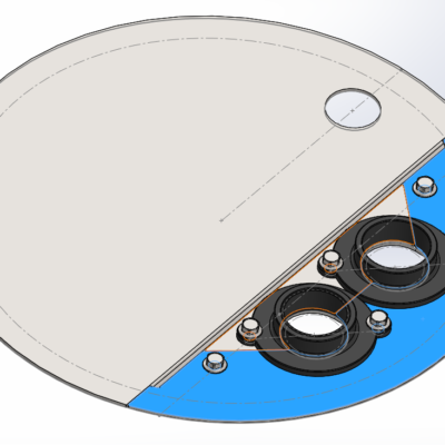
- Stress concentrations around bolt fasteners IN GENERAL.
- This visual cue tells that the bolts and nuts are actually doing something, and the simulation problem was probably set up correctly in this respect. As loads are applied to the object that makes it try to force itself apart from its various pieces, you can see stresses build up around the bolt holes as the fasteners strain to clamp the pieces together. If the study had been set up incorrectly, to bond all the parts together as if each face was perfectly glued, you wouldn’t see stress concentrations as much around bolt holes. It would be more evenly shown across mating faces and edges.
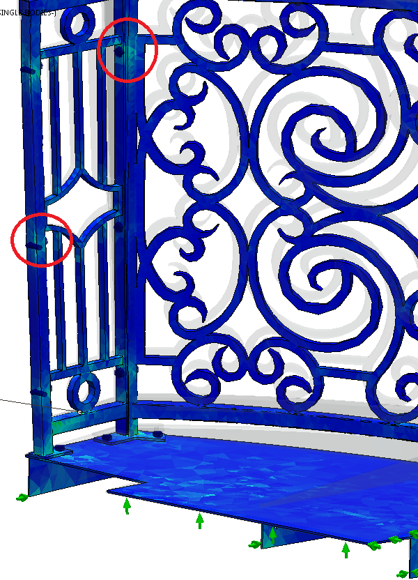
- Stress concentrations around SPECIFIC bolt fasteners.
- Check all parts’ bolt hole stress concentrations. Sometimes a contact set between 2 parts’ interface appears to exhibit a true stress relationship, but then another pair of parts are interacting apparently falsely at their connection points. Check thoroughly for cues, and use the Contact Visualization Plot tool.
- Just because a bolt hole doesn’t exhibit much stress doesn’t mean the study setup is flawed. It may be that the particular loads do not affect some of the connections as much as others. But lookout for discrepancies, and make your decisions on what they mean.
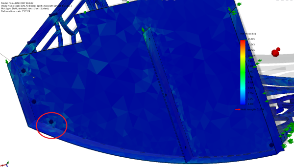
- Stress Is Where You Find It
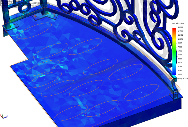
- Concentrating the loads across sets of footprints doesn’t seem to matter. Probably because the steel plate is .188″ thick, and it doesn’t have all the material for grating removed. It’s a coarse mesh, too.
- Some of the problem areas you thought you’d find may not materialize, and some patterns may be a surprise.
- FEA-Inspired Design Changes
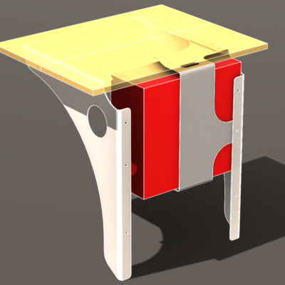
- Stress Plot Visual Cues – See here that the weight is pushing the deck down and the corner of these ribs would be forced into the wall of the building due to a hinge effect from other constraints.
- Here’s an example of FEA simulation driving design changes:
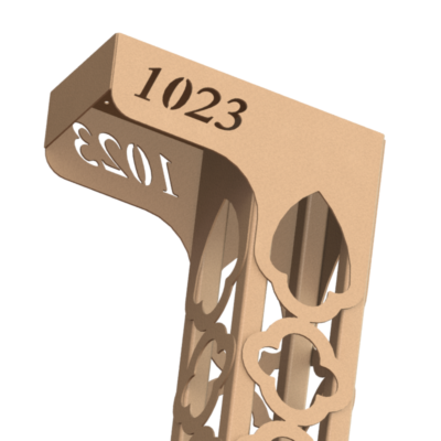
- I think I would do better to add at least a .25″ fillet to the corners of these ribs so if they are installed as to be so close to the building, and are then forced into the siding of said building, that they may not dig into the material with such concentrated forces as at a sharp edge. I would think it’s bad design to see a product installed that unintentionally and needlessly damages the finish of its substrate.
- Another idea would be to continue the skirting around the back of the deck, which would take the interface between the rib ends and building siding out of the equation completely, and may or may not look better aesthetically.




Leave a Reply about how this blog changed your life.