
Global Contacts and Contact Sets
First, Let’s Show What Not To Do (Apparently Contact Sets don’t always override Global Contacts…)
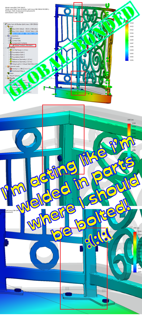
I previously made the mistake of leaving on “Global Contact: Bonded” in this study. I didn’t think it would matter, as there are No Penetration contact sets in the study for all the faces that should have it, and contact sets are supposed to outrank global contacts. But it was obvious when looking at the displacement plot results that this rule was not being observed.
I must admit, I have had trouble getting the solver to exhibit the bonded behavior again to verify it. But it comes out with the following choices: Selected for non-touching faces, within 6mm of each other, to be bonded as incompatible mesh. Not sure why the contact sets didn’t supersede this errant global bonded contact, but you can see what the differences are below.

Here’s with the Global contact on, it makes some parts that should be just bolted together (No Penetration) act as if welded together.
Here’s with the Global Bonded Contact suppressed (and proper No Penetration contact sets in place):

Here’s the Contact Visualization Plot, to show what is happening when the Global Bonded contact is on. The solver thinks, in some areas, the parts are both bonded and not bonded. No wonder it would take so long for the problem to start solving when this was happening. Also, notice all the little red spots on the scrolls on the front rail. I think that’s the “6mm” non-touching faces option trying to weld together all these parts to themselves. This is why the Contact Visualization Plot tool can be very helpful in telling you what SW Simulation thinks the relationships are between parts.

Hopefully this helps as a “What Not To Do with Simulation Contacts” lesson.


Leave a Reply