External Loads
- Gravity was applied to the top plane to account for the weight of the balcony.
- The default for gravity was used. I have not yet tested for residents of Jupiter.
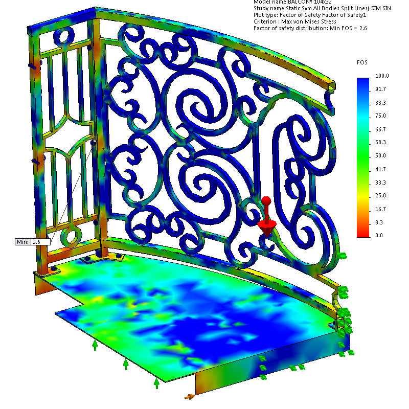
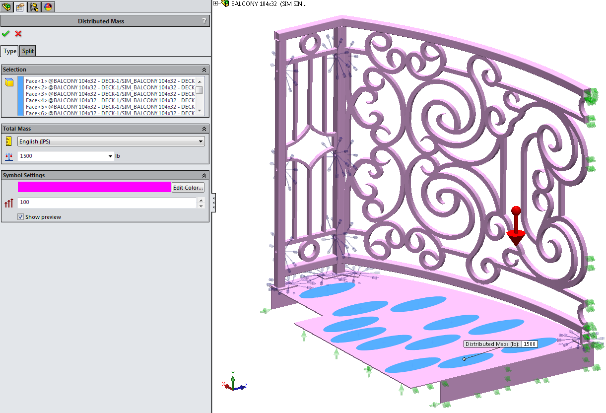
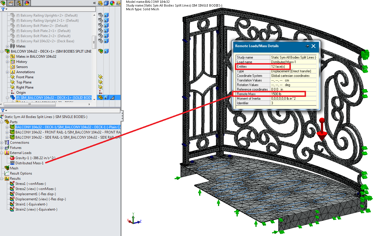
- 1500 lbs of distributed mass was applied to the “footstep” areas (created with a sketch and then converted to split lines).
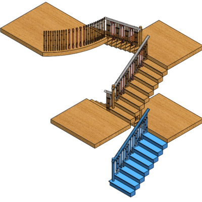
- There are 6 pairs of “feet” on the balcony half. I want to simulate that somehow, on this 20 sq ft balcony, twelve 300-pound guests have shown their utter contempt for the laws of physics and shoehorned themselves onto the deck.
- Since this is a 1/2 symmetry setup, I used 1,500 lbs for weight, because I want to apply 3,000 lbs to the entire balcony.
- Notice how the mesh elements concentrate around the weight-loaded shoe prints.
Fixtures
In addition to the fasteners used, there are some fixture features made to recreate environmental conditions.
All fixtures highlighted in the feature tree will make its arrows appear light blue in the screenshots below.
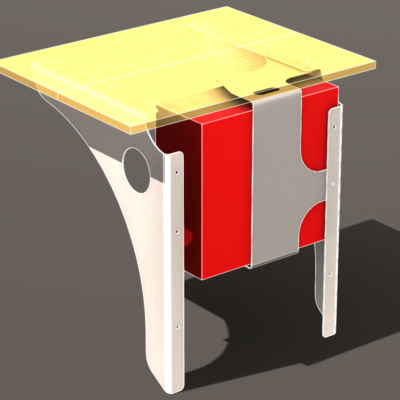
- Side of Building: Though this fixture is named “On Flat Faces” in the tree, it was changed later to “Reference Geometry”, but the tree feature did not rename itself. This fixture is supposed to be the side of the building. If the weight on top of the deck leads to enough deformation, the corners of these ribs will dig into the exterior materials.
- I didn’t use a virtual wall because the solver seemed to be glitchy when I used more than one parallel virtual walls.

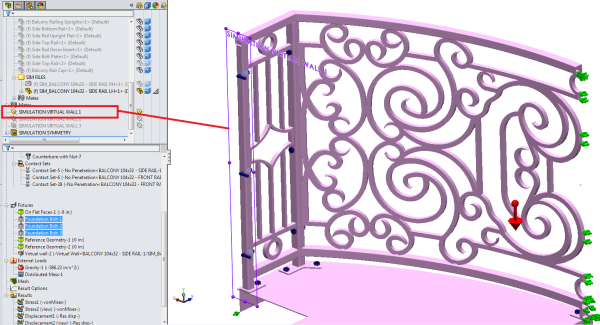
- Makeshift Symmetry Fixture: This fixture will not allow all the bisected faces that resulted when I cut the assembly in half to move toward where the missing half would be. This does the same thing that a “Symmetry Fixture” would do — but sometimes the symmetry fixture won’t work because for some reason SW Simulation doesn’t think you have perfectly cut your geometry in half (or fourths or eighths, I think… I don’t usually have radially symmetrical problems.)
- If you’re trying to use a makeshift symmetry fixture with shells or mixed mesh with shells, you’ll need to grab shell edges instead of faces. You’ll still want to set translation normal to the face (or selected plane) to zero, but you’ll probably also want to set the rotational movement to zero in the other two directions that weren’t normal-to.

- Door Threshold Fixture: The plan is for this edge, and maybe a little more surface area around there, to sit on the door threshold. Thresholds are usually angled downward to shed rain, yet the balcony deck will be level with the world, so it’s likely that only the edge will rest on the door’s threshold.

- Virtual Wall Fixture: I don’t understand why it’s necessary to set up a virtual wall fixture IN ADDITION TO a foundation bolt fixture. I would think it would be assumed that the object will not move through a foundation. But I’ve read several places that in static studies, which allows you to use foundation bolts, you must also set up a virtual wall so the solver understands that the object is up against something.

- Foundation Bolts Fixtures: These are the only thing holding the balcony assembly – hundreds of pounds of steel – to the side of the building. But they’re supposed to approximate 1/2″or M12 lag bolts drilled at least 4″ to 5″ into 2″ x 6″ wood wall studs.
- FYI Tip: You can right-click on a bolt in the tree and copy it, then paste it by right-clicking on “Fixtures” and clicking paste. You’ll have to re-choose the edge or cylindrical faces for the other bolt holes, but all the other options you chose should be there. Nice time saver.
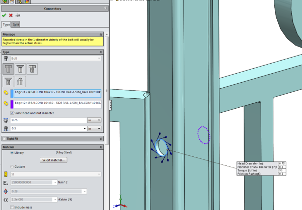
- Connector Bolts with Nuts (Simulation describes as “Counterbore” bolt with nut, but it is not c-bored).
- I changed the shank diameter size to 1/2″ and looked up the head size on a bolt chart.
- I used the default “Alloy Steel” for the fastener material, with its default SolidWorks material attributes.
- I used a bolt torque chart to determine the amount of ft/lbs per square inch for a bolt this size made to Grade 8 standards.
- I left the friction ratio as default.


Leave a Reply