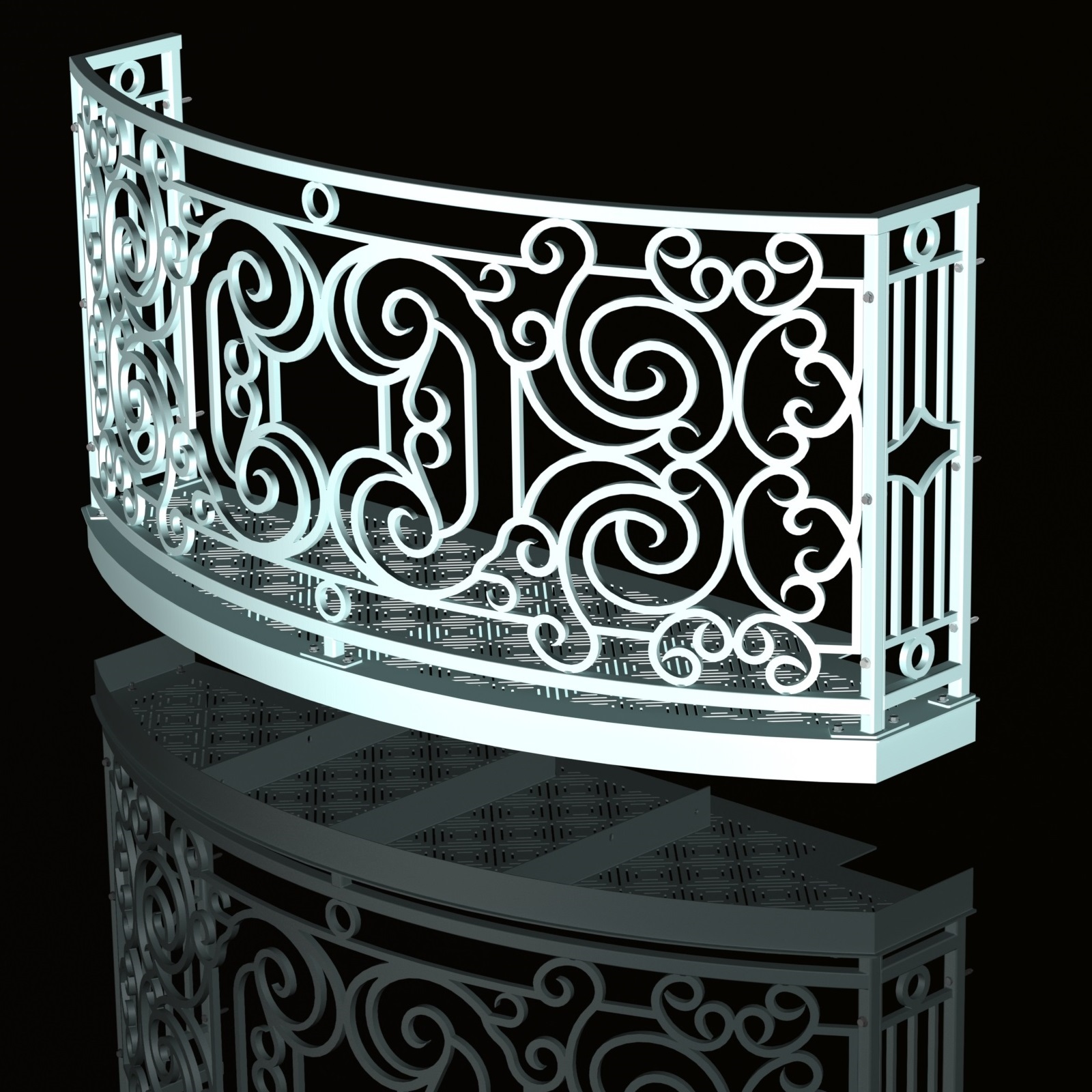
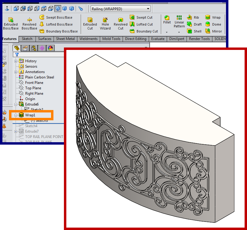
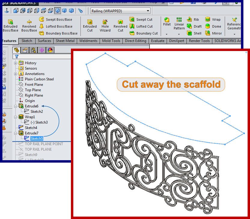
How To Wrap a Sketch in SolidWorks, to Extrude a Curved Railing
Here’s how I did it, anyway. Realize this model was started over 3 years ago from the date of this post’s publishing. I would probably do things differently today, including using the Weldment multibody part file and more “Direct Editing” features, like “Delete Bodies” instead of “Cut Extrude”-ing solids out of existence. But I pulled this file out of the Dusty Old CAD File Shelf and here’s what it is.
The “Missing Link” in My CAD Modeling Style Historical Record.
When I first started modeling in SolidWorks, everything I did was always “Bottom-Up,” creating part files and adding them to assembly files. Sometimes sketches in an assembly file would be a guide or “skeleton”, but anything that created external references was forbidden.
In this section I will blather on about myself, detailing the minutiae of obscure topics with narrow appeal.
I’ve since got into the serious time savings of multibody “Top-Down” part modeling. But before then, this balcony file is sort of a “missing link” in my modeling style evolution, as it’s not exactly a SolidWorks “Multibody Part” nor a “Weldment” file (files made to provide ease of design, fast changeability, with good fit-up dependencies, yet be easily split out into *.sldprt files that Manufacturing and Assembly can best handle).

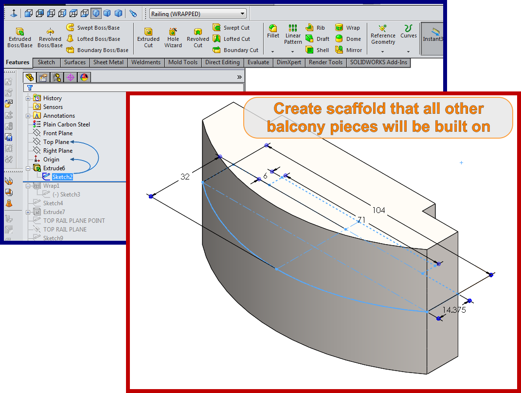
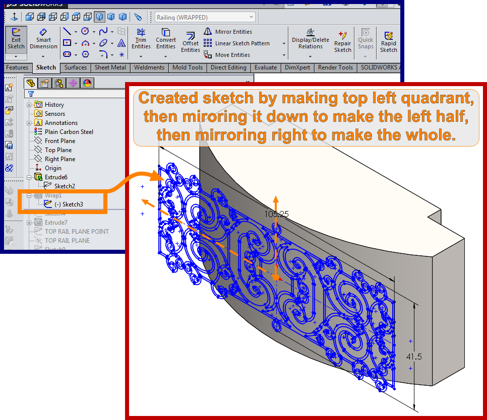
You can see the driving geometry dimensions behind these balcony subassemblies are at the part document level. Many parts can have their geometry changed just by updating one sketch’s dimensions (you guys who’ve done weldment files for many years get it). Most assembly parts are derived from just a couple different part files. The parts (deck grate, upper railing, lower railing, front skirt, side skirt, etc.) appear and disappear according to Configurations which suppress or unsupress features.

Again, I used suppressed features per configurations in a regular part file to create multiple individual piece parts to save out instead of organizing a weldment part file’s cut list of “bodies” into subweldments and either saving them out and/or suppressing them per configurations that are subassemblies, collections of parts, or subweldments. This was my transitional version of Top-Down modeling, the point at which I went from ONLY bottom-up part creation to eventually learning more about how to use the top-down tools in the SolidWorks platform.
I will name this CAD file “Lucy,” as I was listening to the Beatles when I unearthed it.
The funny part is that it’s almost like going full circle, as the 3D CAD platform I taught myself on was SketchUp, and everything was a top-down exercise in that program, at least for me.


Leave a Reply