I felt like this whole balcony extravaganza was getting a little too hysterically long, so I split it into a Design post and an FEA post. If you’re seeing this post first, but want to see The Origin Story of the world famous balcony series, click below:
♦ Curved (Rolled Sheet Steel) Decorative Balcony Designs that Mimic Wrought Iron Fabrication (Go to the balcony design post)
FEA Simulation
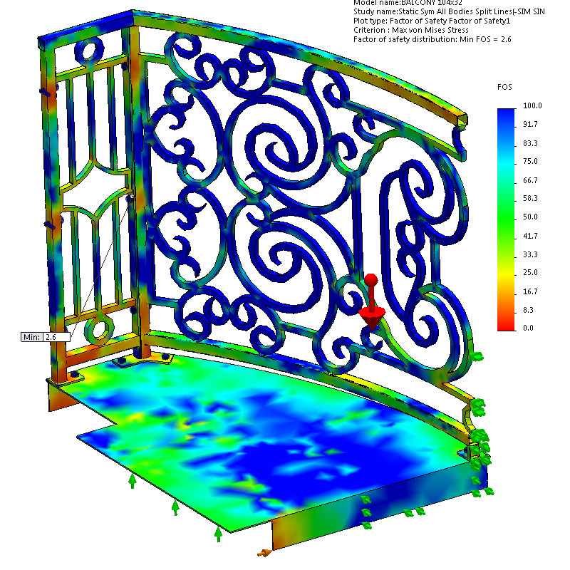
Here’s the meat & potatoes section. I don’t know why I said that. Actually, this is some screenshots and explanations of how I set up a simulation scenario, complete with fasteners, external fixtures, and mass loading. I wanted to safety test this thing to make sure you could park a subcompact car on it before someone’s grandchildren stand on it.
Simulation Problem Setup
Models:
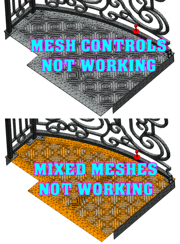
To set this up, at first I kept trying to use the assembly file. This means I tried to mesh all the solid parts of the assembly. Then I tried to create shells and beams and solids and super-fine mesh controls and any and every combination of mixed mesh ever conceived of. There were always problems! I couldn’t get a believable result, if I could complete a solve at all!
Sometimes the road to simplicity is a complicated maze.
And it was all because I really wanted to get that grate deck top to mesh with all the slots in it, because I’m thinking with all that material missing, it will affect the strength, stiffness, and make it act more like a spring than a slab. But it just didn’t want to work, whatever I tried.
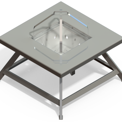
So finally, after wasting way too much time on this, I just created single-body part versions of the 4 bolt-together subassembly weldments (Deck, Front Rail, Side Rail LH, Side Rail RH – and I really didn’t need one of the sides since I cut the railing in half for symmetrical solving). This means each subassembly has a configuration where everything is suppressed except the single-body part file version of itself. And I extruded a boss through the grate on the deck to make it solid.
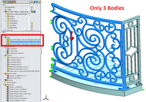
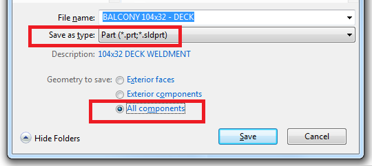
This means there are essentially only 3 bodies in this simulation (after symmetrical cut out completely removes a side rail). I did this by saving the assembly files (*.SLDASM) out to part files (*.SLDPRT) and making sure to choose the little checkbox in the Save As dialog that saves all surfaces and bodies (“All components”). Otherwise, I was getting broken surfaces.
Then I had to do some massaging, adding in bosses, using the “Surface” tab to thicken and merge faces, using the “Direct Editing” tab’s “Combine Bodies” to get bodies to go together into one. This can also be a good diagnostic tool – if you can’t get bodies to combine, they must not be properly merged somewhere. So you’ll need to find a way to make a feature that connects the body to another. Of course, this is all for simplicity’s sake, so hopefully what you’re doing isn’t too complicated or time-consuming. Unfortunately, sometimes the road to simplicity is a complicated maze.

Leave a Reply about how this blog changed your life.